Modbus TCP Power Devices
This section provides background information on Modbus TCP Power Devices 2 of Desigo CC. For related procedures, see the step-by-step section.
For information on naming conventions for names, paths, and other elements, see Common Rules for Names and Paths in the Management System and Naming Rules for Subsystem Elements in Naming Conventions.
Libraries
When you install the management station and select the Modbus TCP Power Devices 2 extension module from the Energy and Power extension suite, the EnergyAndPower _Device_Modbus_HQ_2 library is installed on your system.
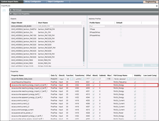
EnergyAndPower_Device_Modbus_HQ_2: This library lists the Object Models associated with the Sentron and Sicam devices.
Device | Object Model | Short Name | Offset | Function Name | Address Profile | |||||||||||||||
Sentron | GMS_MODBUS_ | Sentron_ | 0 | PowerMeterSmall | Full | |||||||||||||||
|
| 1Phase | ||||||||||||||||||
3Phase4Wires | ||||||||||||||||||||
Sentron | GMS_MODBUS_ | Sentron_ | 0 | PowerMeterFull | Full | |||||||||||||||
|
| 1Phase | ||||||||||||||||||
3Phase3Wires | ||||||||||||||||||||
3Phase4Wires | ||||||||||||||||||||
Sentron | GMS_MODBUS_ | Sentron_ | 0 | PowerMeterFull | Full | |||||||||||||||
|
| 1Phase | ||||||||||||||||||
3Phase3Wires | ||||||||||||||||||||
3Phase4Wires | ||||||||||||||||||||
Sicam | GMS_MODBUS_ | SICAM_P850_PM | 1 | PowerMeterFull | Full | |||||||||||||||
|
| 1Phase | ||||||||||||||||||
3Phase3Wires | ||||||||||||||||||||
3Phase4Wires | ||||||||||||||||||||
Sicam | GMS_MODBUS_ | SICAM_Q100_PM | 1 | PowerMeterFull | Full | |||||||||||||||
|
| 1Phase | ||||||||||||||||||
3Phase3Wires | ||||||||||||||||||||
3Phase4Wires | ||||||||||||||||||||
Sicam | GMS_MODBUS_ | SICAM_P855 | 1 | PowerMeterFull | Full | |||||||||||||||
|
| 1Phase | ||||||||||||||||||
3Phase3Wires | ||||||||||||||||||||
3Phase4Wires | ||||||||||||||||||||
Sentron_ | GMS_MODBUS_ | Sentron_ | 1 | PowerMeterFull | Full | |||||||||||||||
|
| 1Phase | ||||||||||||||||||
3Phase3Wires | ||||||||||||||||||||
3Phase4Wires | ||||||||||||||||||||
Sentron_ | GMS_MODBUS_ | Sentron_ | 1 | PowerMeterFull | Full | |||||||||||||||
|
| 1Phase | ||||||||||||||||||
3Phase3Wires | ||||||||||||||||||||
3Phase4Wires | ||||||||||||||||||||
Sentron_ | GMS_MODBUS_ | Sentron_ | 0 | PowerMeterFull | Full | |||||||||||||||
|
| 1Phase | ||||||||||||||||||
3Phase3Wires | ||||||||||||||||||||
3Phase4Wires | ||||||||||||||||||||
Sentron_ | GMS_MODBUS_ | Sentron_ | 0 | PowerMeterSmall | Full | |||||||||||||||
Full_RTU | ||||||||||||||||||||
|
| PhaseL1 | ||||||||||||||||||
PhaseL2 | ||||||||||||||||||||
PhaseL3 | ||||||||||||||||||||
PhaseL1L2 | ||||||||||||||||||||
PhaseL2L3 | ||||||||||||||||||||
PhaseL1L3 | ||||||||||||||||||||
3Phase3Wires | ||||||||||||||||||||
3Phase4Wires | ||||||||||||||||||||
Sentron_ | GMS_MODBUS_ | Sentron_ | 0 | PowerMeterSmall | Full | |||||||||||||||
|
| 1Phase | ||||||||||||||||||
3Phase4Wires | ||||||||||||||||||||
Sentron_ | GMS_MODBUS_ | Sentron_ | 0 | PowerMeterBase | Full | |||||||||||||||
|
| 1Phase | ||||||||||||||||||
3Phase3Wires | ||||||||||||||||||||
3Phase4Wires | ||||||||||||||||||||
Sentron_ | GMS_MODBUS_ | Sentron_ | 1 | PowerMeterSmall | Full | |||||||||||||||
|
| 1Phase | ||||||||||||||||||
3Phase3Wires | ||||||||||||||||||||
3Phase4Wires | ||||||||||||||||||||
MD_BMED | GMS_MODBUS_ | MD_BMED_PM | 0 | PowerMeterSmall | Full | |||||||||||||||
|
| 1Phase | ||||||||||||||||||
3Phase3Wires | ||||||||||||||||||||
3Phase4Wires | ||||||||||||||||||||
MODBUS | GMS_MODBUS_ | 9410_PM | 1 | PowerMeterFull | Full | |||||||||||||||
|
| 1Phase | ||||||||||||||||||
3Phase3Wires | ||||||||||||||||||||
3Phase4Wires | ||||||||||||||||||||
MODBUS | GMS_MODBUS_ | SEM3_1_Phase | 0 | PowerMeterMultiPhases | Default | |||||||||||||||
MODBUS | GMS_MODBUS_ | SEM3_2_Phase0 | 0 | PowerMeterMultiPhases | Default | |||||||||||||||
MODBUS | GMS_MODBUS_ | SEM3_3_Phase | 0 | PowerMeterMultiPhases | Default | |||||||||||||||
MODBUS | GMS_MODBUS_ | SEM3_Controller | 0 | PowerMeterDeviceMultiPhases | Default | |||||||||||||||
The following pre-defined poll groups are defined with the Modbus TCP Power Devices 2 extension module.
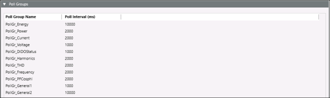
These poll groups are associated with the properties of the devices. Once the devices are created on the management platform, the mapped poll groups are created in the system.
You can modify the interval for a poll group by navigating to Project > Management System > Servers > Main Server > PollGroups.

NOTE:
For all the above devices the value of the littleEndianRegister needs to be set to 0 before starting the project.
Known Limitations
For the meter types Sicam P850 and Q100, the displayed energy values are not actually provided by the meter register directly. The raw register data are scaled for correct display in the management station graphic, but any functions like trending or reporting will still use the raw, un-scaled data. These are not representative of the real energy values.
CSV Data
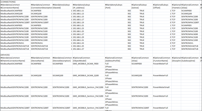
In order to create instances of the Modbus TCP Power Devices, you must create the engineering data in the form of a comma-separated value (CSV) file. A CSV file contains data in which values are represented as text and separated using a separator such as comma (,). This format can be easily edited in simple text editors such as Wordpad or Notepad. More elaborate editing can be done using advanced word processing tools, like Excel. The Importer can parse CSV files which only use the comma (,) as the separator.
The CSV file must consist of the following components:
- Name of the Modbus Library
- Name and details of the interface where you want to create the devices
- Names and details of devices
For details on the number of fields for library, interface and devices entries in the CSV file, see the Engineering Data section in the Modbus Help.
The following example shows a sample CSV file that is used to create instances of devices.